Hi, I just started to test pupil invisible, and the scene & eye cameras are not being recognized in the app, I'm using the black USB-C cable and have enabled the OTG.
Hi @user-e93961! Can you also confirm that you are connecting the device to a OnePlus 6 or OnePlus 8 phone?
Hi Marc, I'm using a OnePlus6 with Android version 8.1.0. And the app version is 1.4.30-prod.
Hi, This might sounds like a silly question as i am new to analysing data from this device. I am using an on-screen display of an image and i have used the marker mapper enrichment. on the image i am displaying, there are specific marked points and i am interested in finding out how much time the participant spends looking at these particular points. I am hoping someone could tell me which metric would be best to use to gather this information i.e surface position? gaze.csv? And if there is a way to determine what the exact coordinates of each location on my image would be? Hope this makes sense, any help is greatly appreciated!
Hi @user-6826a6! As a first step you could read this article, which is addressing the problem you describe I think. The article describes how this is done when using the Reference Image Mapper rather than the Marker Mapper, but the outputs of both enrichments are similar and the described approach can be adapted to work with the Marker Mapper. https://docs.pupil-labs.com/alpha-lab/gaze-metrics-in-aois/
The Marker Mapper provides you with gaze data on a surface (in your case the image) in normalized coordinates. If you know where the individual points of the image you want to compare are in those coordinates, you can filter the data accordingly and then calculate e.g. the total fixation duration to estimate how long each participant looked at each point.
Let me know if you have any follow-up questions!
Hi Marc, thank you so much. it looks like this will be very helpful to explore. I don't know if i have missed something but i'm not sure what to run the python code in? I have created the image mapper enrichment and can download the CSV files etc but it feels like maybe ive missed a step as im not too sure how to go from the cloud enrichments to the actual analysis? Sorry if thats a silly question
Hi @user-6826a6 ! If you prefer vanilla python over Jupiter notebooks, have a look here https://gist.github.com/mikelgg93/a250811d59885e791cbeeb99fd12ef55
I will have a look into this thank you so much!
Otherwise, you can directly call the .ipynb file from and IDE like vscode
Have you worked with Python before? Some additional context: You need to download the data to your computer and execute the Python code there as well. A Jupyter notebook is a slightly special Python environment often used in scientific work. The vanilla Python code could be executed with any Python interpreter from within an IDE or from a terminal.
I have a little experience with python and online jupyter notebooks from a course i did a while back. Thank you for all your help.
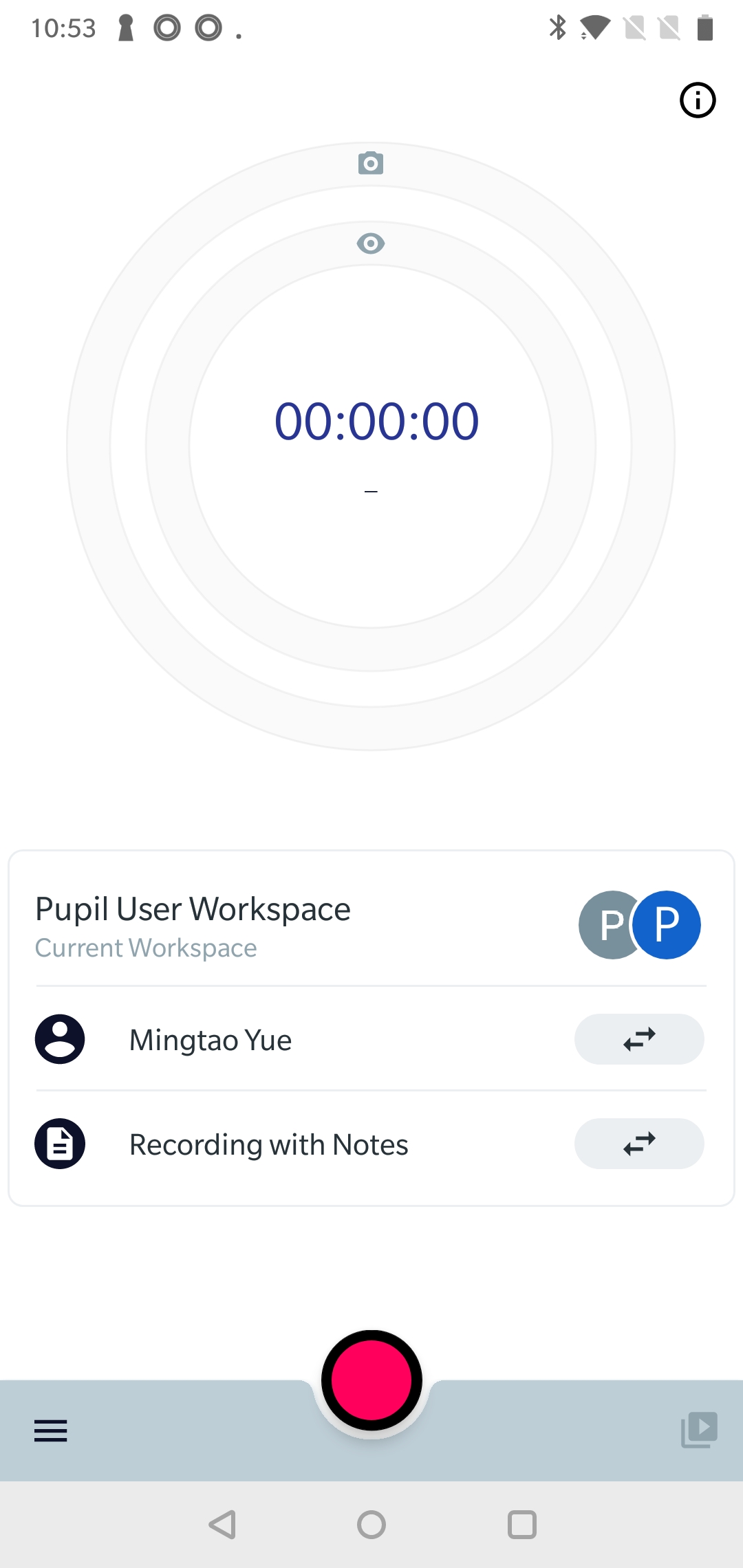
Hi @user-e93961 👋. Can you elaborate on what you mean by the eye cameras not being recognised? Does the gaze circle show in live preview mode? It might help if you could share a screenshot demonstrating the issue
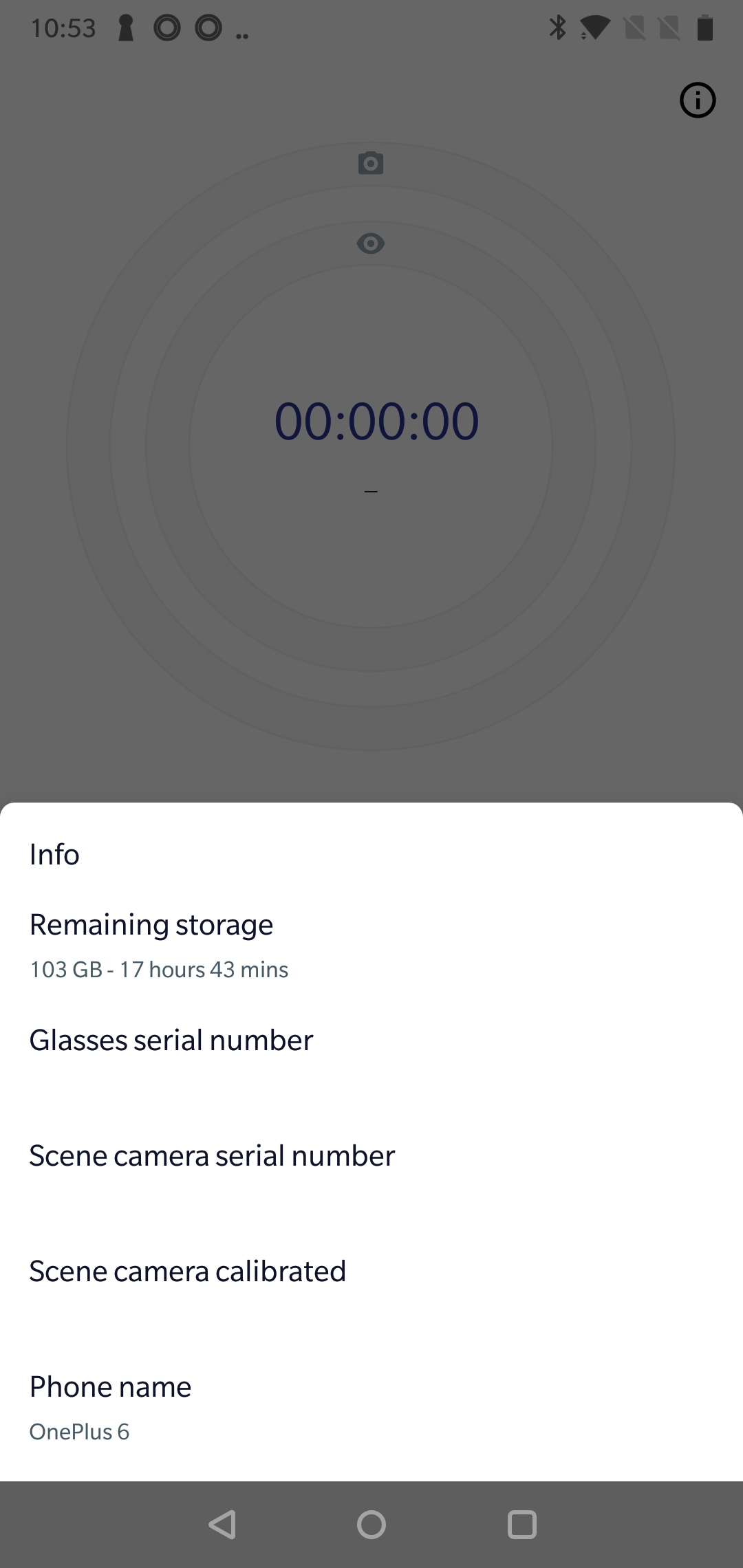
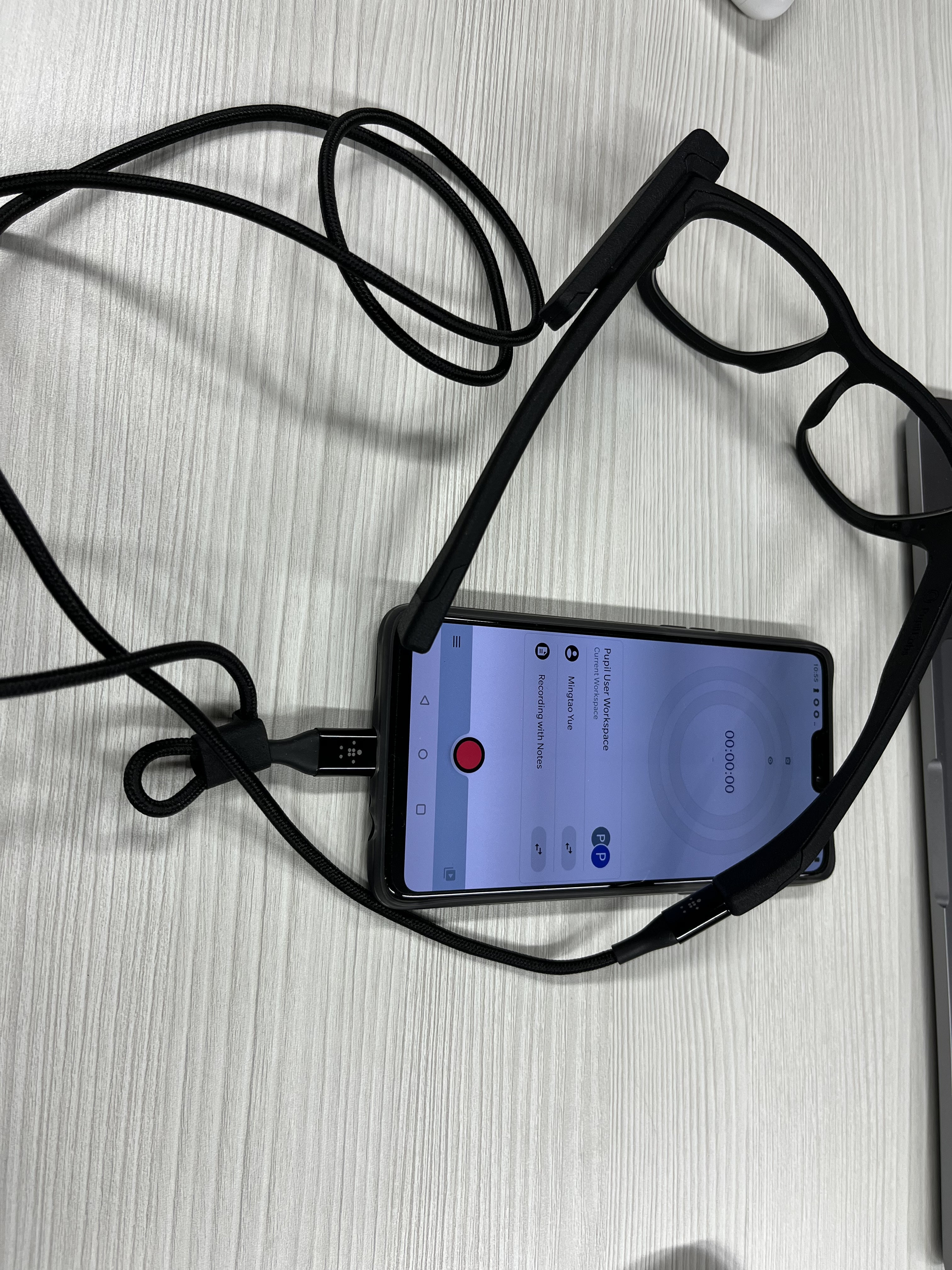
Hi Neil! After I connected the phone and eye glasses using the black USB-C cable, the scene camera icon, eye camera icon and preview button were still grey, so I couldn't enter preview mode. Also I clicked the info button and the serial number of glasses and camera were not showing, so I was assuming that the glasses were not being recognized by the phone. I tried to use the cable to connect other devices and it worked well, maybe the problem was in the eye glasses. Btw does the eye classes need charging, or is there any switch on the glasses?
Hi Neil After I connected the phone and
Hi,
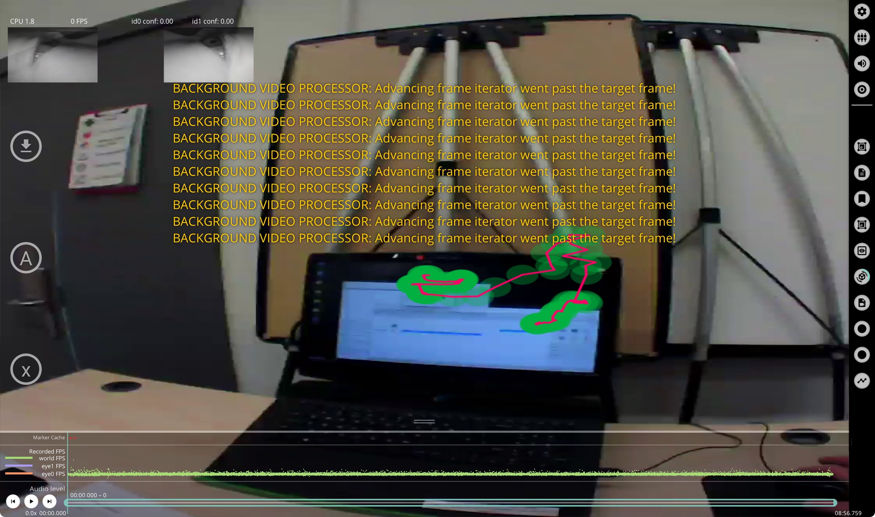
I would like to edit the scene video (named "PI world v1 ps1.mp4" on my side ), for example, to increase the contrast and blur the faces in the video. However, after editing the video using either Adobe Premiere Pro or After Effects, exporting a new video, and replacing this new video with the existing one, the Pupil Player (ver. 3.5.7 on Mac OS) cannot properly read the edited video. The error message that I get is "Background video processor: Advancing frame iterator went past the target frame", see the attached screenshot.
I checked the number of packets/frames in both videos with the following script, and both videos output the same number:
ffprobe -v error -select_streams v:0 -count_packets \ -show_entries stream=nb_read_packets -of csv=p=0 input.mp4
I would be glad if I can learn more about this issue, and potential solutions.
Thanks!
Hi @user-ab605c. The recommended workflow in this case would be to export the videos with gaze overlay from Pupil Player and subsequently do post-processing/editing in third-party software. Already edited videos might not be expected to work for a variety of reasons.
Hi Neil, thanks! There are two main reasons why I wanted to edit raw videos: I wanted to share the raw data of recordings in a public data repository, and ideally I would like to blur other people recorded with the scene camera. Also, I wanted to check whether I can enhance the april tag detection, by for example changing contrast levels in the video footage or layering an additional set of april tags using motion tracking in video editing software. If it is easy to point out some obvious/potential reasons behind this issue, I would be glad to hear them and try to resolve it!
Is there a reason you need to blur faces before working with the recordings in Player?
@user-ab605c I'll jump in and say that I'm struggling with the same issue, in another context. I want to calculate the optical flow in sequential frames. This requires using a library to decode the frames, compute the new derived frame of optical flow, and then transcode the flow frame into a new video that preserves the frame timing of the original video. Even with very low-level control over the frame and packet presentation time stamps and decoding timestamps, I can't Pupil Player to accept my output. I get the same error.@papr is being very helpful over in 🥽 core-xr , but it's a work-in-progress.
Hi performLabRIT, thanks! Similarly, I tried to control/equate most aspects that I can think of within the video editing software (and definitely not as low-level control as you did), including random or potentially irrelevant things like copy-pasting metadata. I will check the vr-ar channel in detail, to get additional insights!
@user-ab605c FWIW, video timing is bonkers. Just zany. Keep in mind that, when a video is compressed, each frame is actually a franken-frame that has borrowed visual patches of data (packets) from from previous frames and from upcoming frames. It's a quilt of space-time-violating craziness.
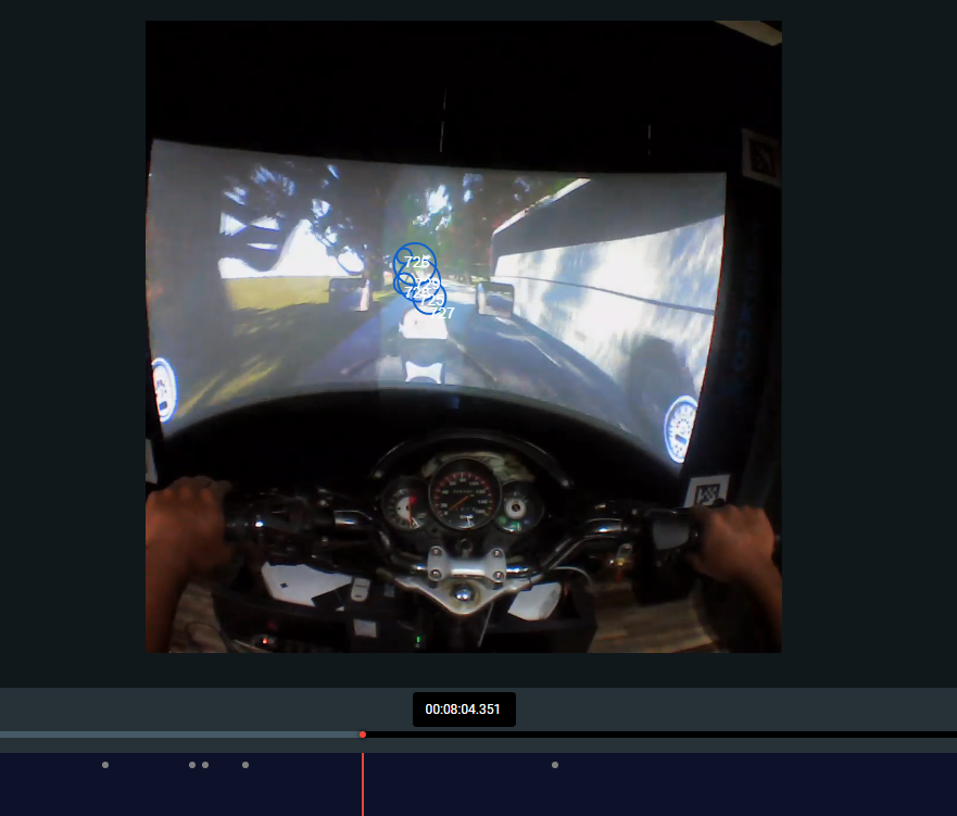
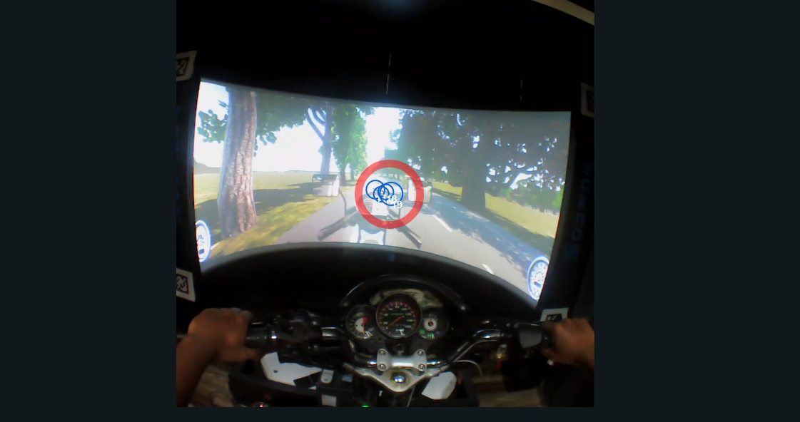
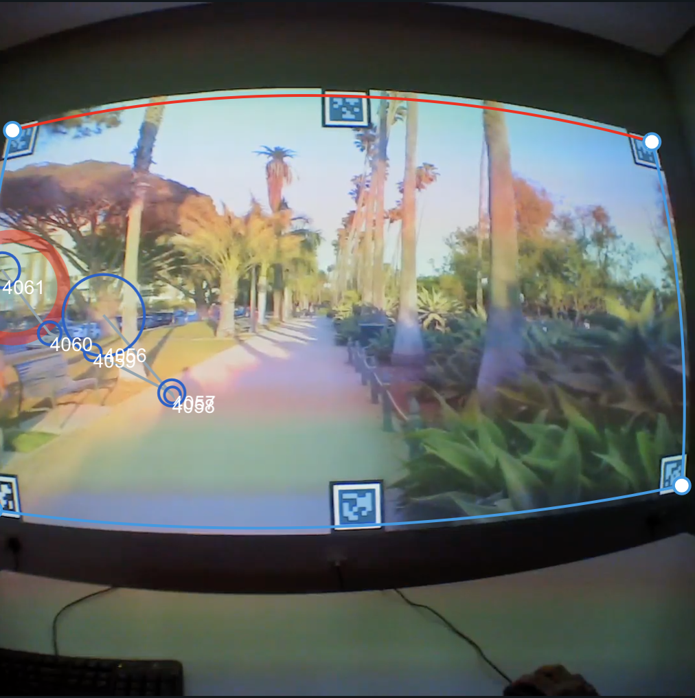
Hi, I have collected data using pupil invisible. I placed 4 markers (QR code) around the desired simulator (computer) screen. However, in the collected data, all the four markers are not visible all the time as the simulator screen is very large (image attached). Therefore, while creating "Marker Mapper" enrichment, my surface position is not anchored, Hence I am not able to interpret gaze data generated accurately from the enrichment. is there any way to resolve this issue? If not.... Is there any way I can use the gaze data obtained from the raw data export? There the gaze data is in reference to world eye camera, is there any way I can account for slight head movements using roll/pitch of head from imu sensors?
@marc Hi, In addition to the above query I also have one doubt regarding Marker Mapper enhancement. what if the four markers are placed in a way that they make a trapezoid shape (not in rectangle), is there any documentation regarding: how the calculation of gaze points is done in reference to the placed marker (QR Codes)?
Hi @user-208db6! Visibility of at least two markers in the frame at all relevant times is a requirement for the Marker Mapper to work. When working with displays, especially large ones, this can challenging to achieve, but I have a few tips.
Regarding your question about the trapezoid, such a placement is not a problem. In theory, even just 1-2 markers would be enough and any additional marker is just for robustness in case some are not detected or are not visible in some of the frames.
We do not have a white paper available on how the algorithm works exactly, but the gist is as follows: The markers need to be placed on a planar surface. The algorithm detects the markers and the exact pixel positions of their corners. Using those corner detection the algorithm calculates a homography that maps points from scene camera coordinates to "surface coordinates".
A few notes/tips: - In your case the surface does not seem to be planar, so this would distort the mapping if you interpret it in pixel coordinates on the rounded screen. - To help ensure markers are always visible, you could place more markers. They do not have to be in the corners, but could be anywhere within the surface plane. You could place them all around the edge of the screen. In theory you could place them inside of the screen, although that is of course undesirable in this case. - Bad camera exposure can also reduce the number of detected markers when working with screens that are bright compared to the environment. You could switch to manual exposure and tune the image a bit to ensure the markers are visible (the screen might be blown out a little then).
Hello! I am trying to create a stimuli in psychopy with the pupil invisible eye tracker. Is there any way to start a recording from psychopy? I have already looked at the simple API, however, this code only works in jupyter notebook. I ideally want my code for the eye tracker to run in psychopy, so that everything is coming from one source. Thanks in advance.
Hi @user-328c63! The real-time API should work from any other Python program as well.
Make sure the API module is installed in the Python environment via
pip install pupil-labs-realtime-api
And also remove the following lines from the code if not working in a Jupyter Notebook
# The two lines below are only needed to execute this code in a Jupyter Notebook
import nest_asyncio
nest_asyncio.apply()
If you still have trouble, let us know what error you get exactly!
Sidenote: Note that when you are interested in mapping gaze to a computer screen, you'd need to use a gaze mapping tool like the Marker Mapper (in Pupil Cloud) first. Real-time implementation of such tools exist, but they are not directly integrated with Psychopy.
@nmt @marc @user-d407c1 Hi, I'm trying using python with frame work to custome and visualize the stream data from invisible glasses connect with my PC by USB! Can you suggest for me some libraries sand example codes to do that ?
Hi @user-277de7! To stream data in real-time, you should use the real-time API, which is documented here: https://docs.pupil-labs.com/invisible/real-time-api/introduction/
Note that this API does not stream over USB, but only through the local network. This can be done either via WiFi, or an ethernet cable. Gaze data can not be calculated unless the Pupil Invisible device is connected to a Companion phone with the Pupil Invisible Companion app installed on it.
Using the IMU data to map gaze data to a screen is not easily possible. Assuming you had very little head movement you could probably devise a calibration procedure that kinda works, but we do not have something you could use out of the box.
Hi! I am using the Marker Mapper and I read that in order to do the Heatmap of the surface, I need to go to the Surface Tracker menu and enable it. Unfortunately, I cannot find where this Surface Tracker menu is, I haven't found it on Pupil Cloud. I could see it mentions a plugin, but I don't know where to find it. Could you help me out?
Hi @user-6e1fb1! Note that the Marker Mapper and Surface Tracker are different things. They implement similar algorithms, but the Marker Mapper is an enrichment within Pupil Cloud and the Surface Tracker is a plugin in Pupil Player!
To get the heatmap for the Marker Mapper in Pupil Cloud you need to navigate to the enrichment list of your project, which contains the Marker Mapper enrichment. Right-click on the enrichment and select "Heatmap". Nothing needs to be enabled to make this available.
Oh yes, right, thank you! One more question, I put the marker mapper on multiple videos but it only shows me the heat map of one and while displaying the recordings on the side, it doesn't allow me to pick the one I am interested in
In the enrichment list, please check if the number of sections noted there corresponds to the number of recordings you think you have computed the enrichment for. Please also confirm here that the enrichment is fully computed for all recorings, i.e. you have a checkmark on the very right of the enrichment and the "Start calculation" button (the play button) is greyed out.
Well it looks like it computed the enrichment for all the videos in the folder and not just the one I chose to determine the surface. And the enrichment is fully computed.
@user-6e1fb1 I see! The enrichment will be calculated for all recordings in the project that match the pair of events you select when creating the enrichment. Assuming you chose the recording.begin and recording.end events for the enrichment, it will be calculated on every recording in the project, because every recording has those events.
If the enrichment has been calculated for every recording, the heatmap should be calculated using all recordings too though (unless you filter the recordings by typing something into the search filter!).
Okay, and the search filter refers to what exactly?
I mean this search bar in the heatmap viewer
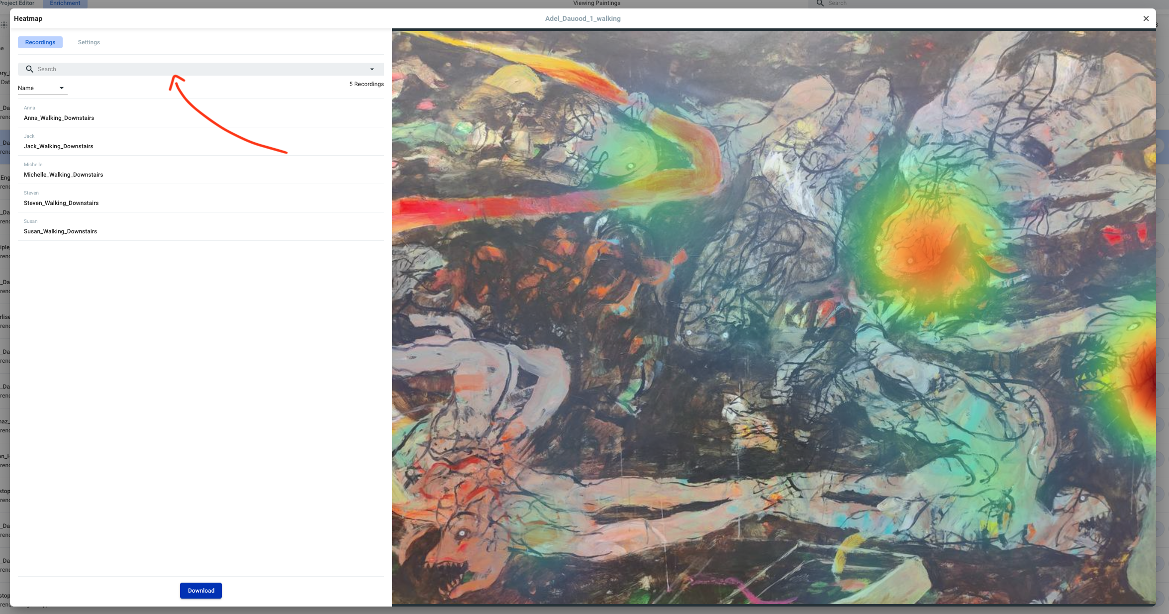
Can you see all your recordings in the list below the search bar?
Yes I can see all the recordings but only the heat points change when I type in the search bar and not the image
The heat values correspond to the aggregated data from all the recordings in the list on the left (all the recordings that make it through the filter). The image used for the heatmap of the Marker Mapper is an automatically generated crop from the scene video selected during enrichment creation. This image serves as example representation for the tracked surface and will never change. Currently there is no way of influencing which frame is used for the crop.
The heatmap download contains a semi-transparent image with only the heat values though, which you could use to overlay it on your own custom crop.
Hi @marc! Thanks for your reply. I have successfully installed pupil-labs-realtime-api, but when I run the "from pupil_labs.realtime_api.simple import discover_one_device" code, I get this error: " from pupil_labs.realtime_api.simple import discover_one_device ModuleNotFoundError: No module named 'pupil_labs'". It works when I use jupyter notebook, but it does not work in psychopy.
You'll probably have to install the API module in your PsychoPy environment
Hi! I copied recordings from the Pupil Invisible Companion Device to my PC via USB. Is it possible to upload the recordings from there to Pupil Cloud or is this only possible by using the Companion App?
Hi @user-bda200! That is only possible via the Companion app. Unless you have explicitly deleted the recordings from the in-app menu, they should still be there though!
Morning! one for the wish list : exports from the cloud and capture the tags attached to the recording please?
Hi @user-df1f44! would you mind logging your request here https://feedback.pupil-labs.com/ ?
Hi there! I have recently been encountering some issues with our eye-tracking glasses. During a session, we have received a notification that an "unexpected error occurred". There is no error code provided and it has led to several sessions of data being lost. Is there a way to prevent this in the future?
This could be a USB connection issue. Please reach out to info@pupil-labs.com in this regard 🙂
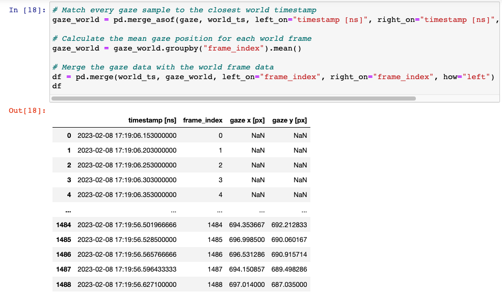
Hello, is there any way I can connect the pupil labs device to the same external clock as my computer? Ideally, I want my time output of the eye tracker to match the output of an additional device I am using in tangent with the eye tracker. I have already tested this code that uses pd.merge, but that time zone is not what I want/am confused on what that time zone is. In the documents it says we're using the nearest time zone, but I want to specify which time zone. Thank you in advance.
Can you please confirm which Pupil Labs eye tracker you're using?
Hi everybody. Is there a way to download the video from cloud exactly like this ? I mean with fixation and relative numbers? I cannot do it. In core player. Or probably I’m not able to.😊
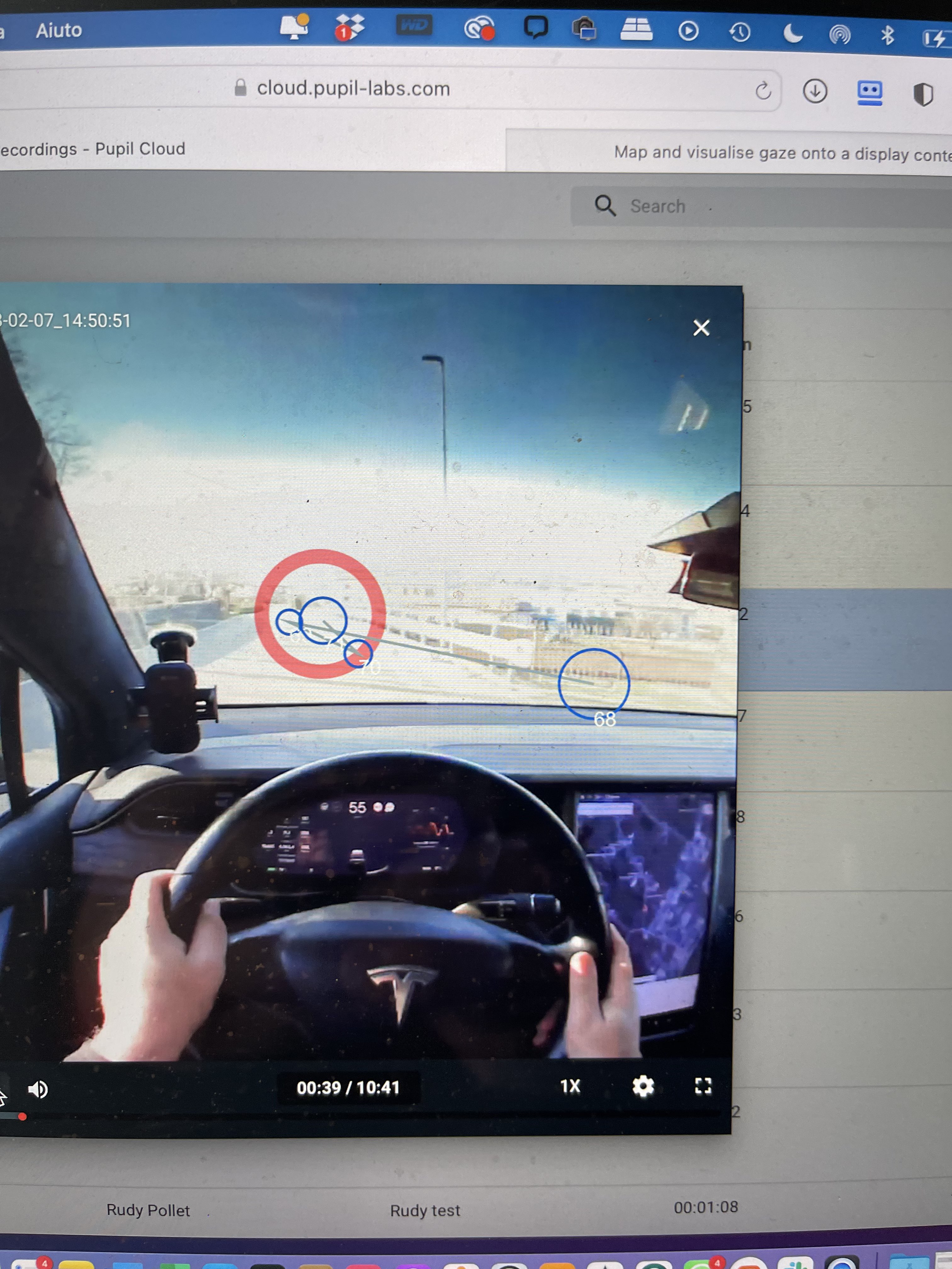
Hello, I'd like to have the same output (with fixations and lines.) When downloaded from the Pupil Cloud, it only has the gaze overlay. Does anyone know where we can get this?
I tried to create this layout on the Pupil Player windows, but "Fixation Detector" is nowhere to be found. The only item I could find was "Fixation Circle," which doesn't appear to differ from gaze circle in any way.
Hi @user-6e0242 and @user-fb64e4, we are working on adding an easy way to download that rendered visualisation, coming soon ™
In the meantime, you can make a screen record (using the screen recording app on Mac or a tool like OBS in any OS) or use the downloaded raw data and create your own visualisation using for example python and openCV.
Hello, our autism_Lab uses Pupil invisible to track gaze and fixation on faces. The enrichment tool face-mapper is very helpful. Unfortunately, when I download the enriched file, it only exports "face_detections.csv" and "gaze_on_face.csv" but not the "fixations_on_face.csv", which is crucial for our research question. Anyone an idea on how to get to that data? Please keep it simple, I am a clinician and no data expert 🙂
Could you please write to info@pupil-labs.com with your enrichment ID? You can find it by right clicking on the enrichment (on the enrichment’s page) and then on under details
The eye cameras are always sampling at 200 Hz, though. That's how we're able to reprocess the eye videos in Cloud to produce 200 Hz gaze data
@marc Hello. I am having trouble figuring out where (0,0) would be when the red line is on the bottom. Is (0,0) the top left and (1,1) the bottom right? When the red line was at the top of the laptop, my gaze coordinates were not aligning with where the participant was supposed to be looking at. However, after flipping the red line to be on the bottom, the gaze coordinates aligned with what was visually being shown by the red regression circle during a recording. Ideally, I really want the bottom left corner to be (0,0) and top right to (1,1). How can I change the settings to make this the case.
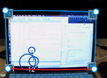
Hi @user-328c63! The red line is supposed to mark the top edge of the surface. And with that definition of the top in mind, the top left corner is defined as (0,0). I'd recommend moving the red edge back to the top.
In your screenshot the top edge is at the bottom, so the surface coordinate system is 180 degrees rotated in relation to what one might expect. With this setup the "top left corner" is in the bottom right. The coordinates of the shown fixations should be about (0.8, 0.1) with this configuration.
When the red line was at the top of the laptop, my gaze coordinates were not aligning with where the participant was supposed to be looking at. Could you elaborate what exactly was wrong?
Hi, I recently started getting recording failures with the Pupil Invisible. The Companion device is an Oneplus 8 with Android 13 and app version is 1.4.30-prod. I mindlessly updated to Android 13 when I got the update prompt so I guess this is the reason? Do I need to downgrade?
Hey @user-06f807 👋. We support Android 11 on OnePlus 8. Check out this section of the docs for instructions on rolling back: https://docs.pupil-labs.com/invisible/glasses-and-companion/companion-device/#android-os
Hi. I did a measurement experiment using pupil invisible. In two of these measurements, my guess is that the smartphone generated a lot of heat, so the measurement was terminated prematurely. When the result directory generated by those measurements was dropped on the Pupil Player screen, the following errors occurred and the video could not be viewed. Is it possible to recover these data to watch videos or get gaze_positions.csv? Thanks.

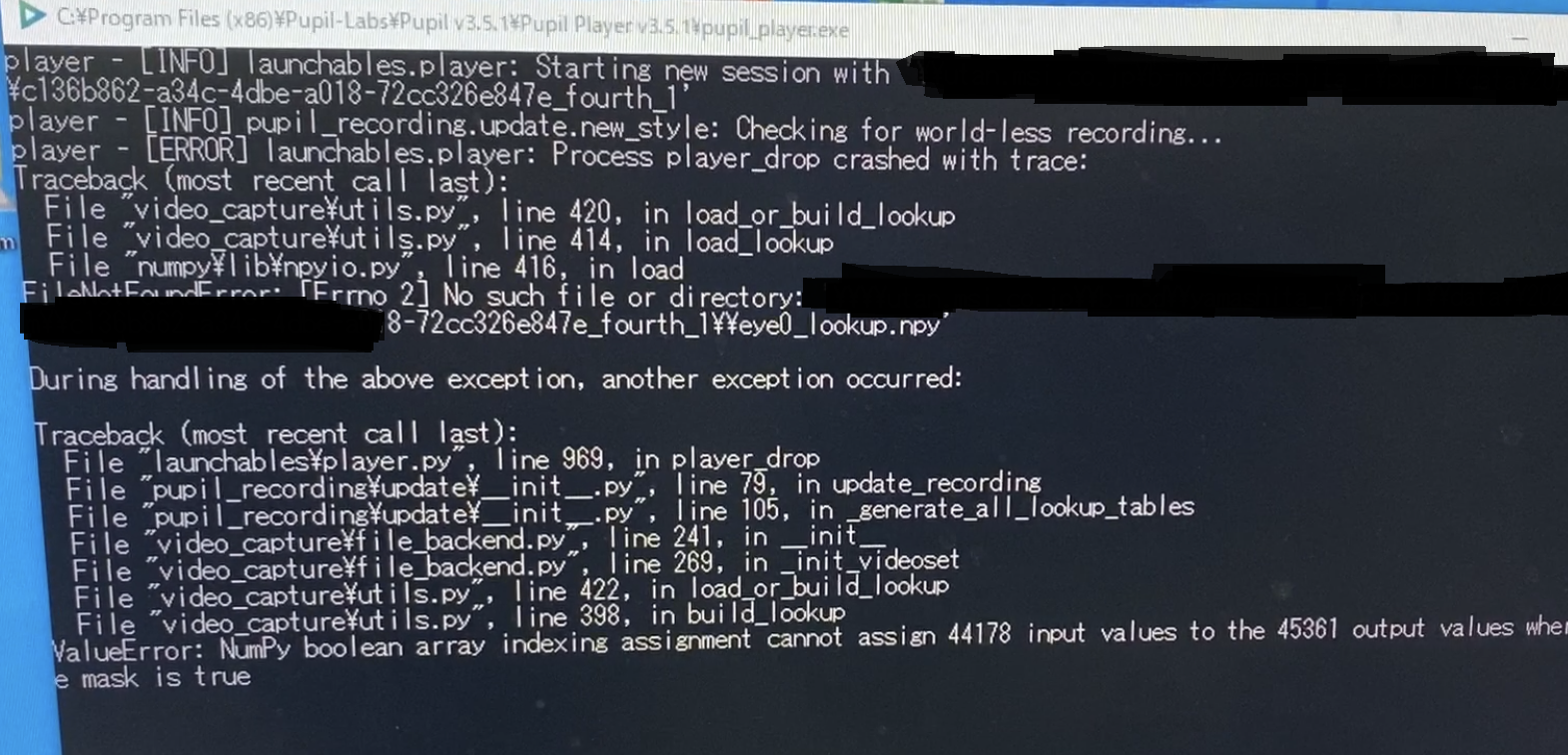
Hey @user-cf4282 👋. Please contact info@pupil-labs.com in this regard
Hello. I am currently using a pupil invisible headset. I am interested in collecting data with the pupil invisible, as well as some other sensors, only when triggered (e.g. from a keyboard button). Therefore it would be convenient to collect data through a PC in Python. I have found some Real-Time API examples (https://docs.pupil-labs.com/invisible/real-time-api/introduction/). However, I only found explanations for acquiring frames from the world camera and the predicted gaze. Is it also possible to acquire IR eye frames from the left and right eye cameras? Is it also possible to acquire the IMU sensor samples? Moreover, is there another app or library, similar to the Pupil Core Record, where I can directly plug the headset into the computer and acquire data, without having to connect it to the android smartphone and connect to the same network.
Hi @user-c71d5e! - It is not possible to stream eye video vie the real-time API, but the legacy API does support it. See here: https://docs.pupil-labs.com/invisible/real-time-api/legacy-api/ - Streaming IMU data via any of the APIs is not supported (the data is included in the recording files though of course). This will only be supported for the Neon device once it comes out. - Plugging the headset directly into another device than the Companion phone is mostly not supported. While obtaining video data is possible, no gaze data can be computed.
Invisible streaming / sync
Hello! Is there a way to attain the confidence scores of the gaze coordinates for the eye tracker? I think I found documentation for other devices, but I can't seem to find one for pupil invisible. Thank you.
Please refer to this message for reference: https://discord.com/channels/285728493612957698/633564003846717444/843764037883265035 🙂
Hello! picking up the thread from @user-328c63 I also have a question about the precise coordinates of surface mapper. For context, we recorded ET data of participants looking at projection screen, where we had added 6 apriltags (image 1). We now want to establish which pixel(s) participants where looking at. We have data for each pixel (e.g. colour) in 1920*1080, while surface mapper exports in 0-1 normalised data. we can do the conversion but we need to know the following: where precisely is the 0,0 with respect to the april tag? end corner? midpoint? I created a little diagram to facilitate your response. (these are the exact april tags we used)
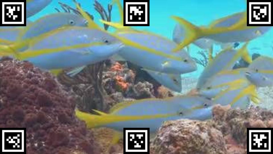
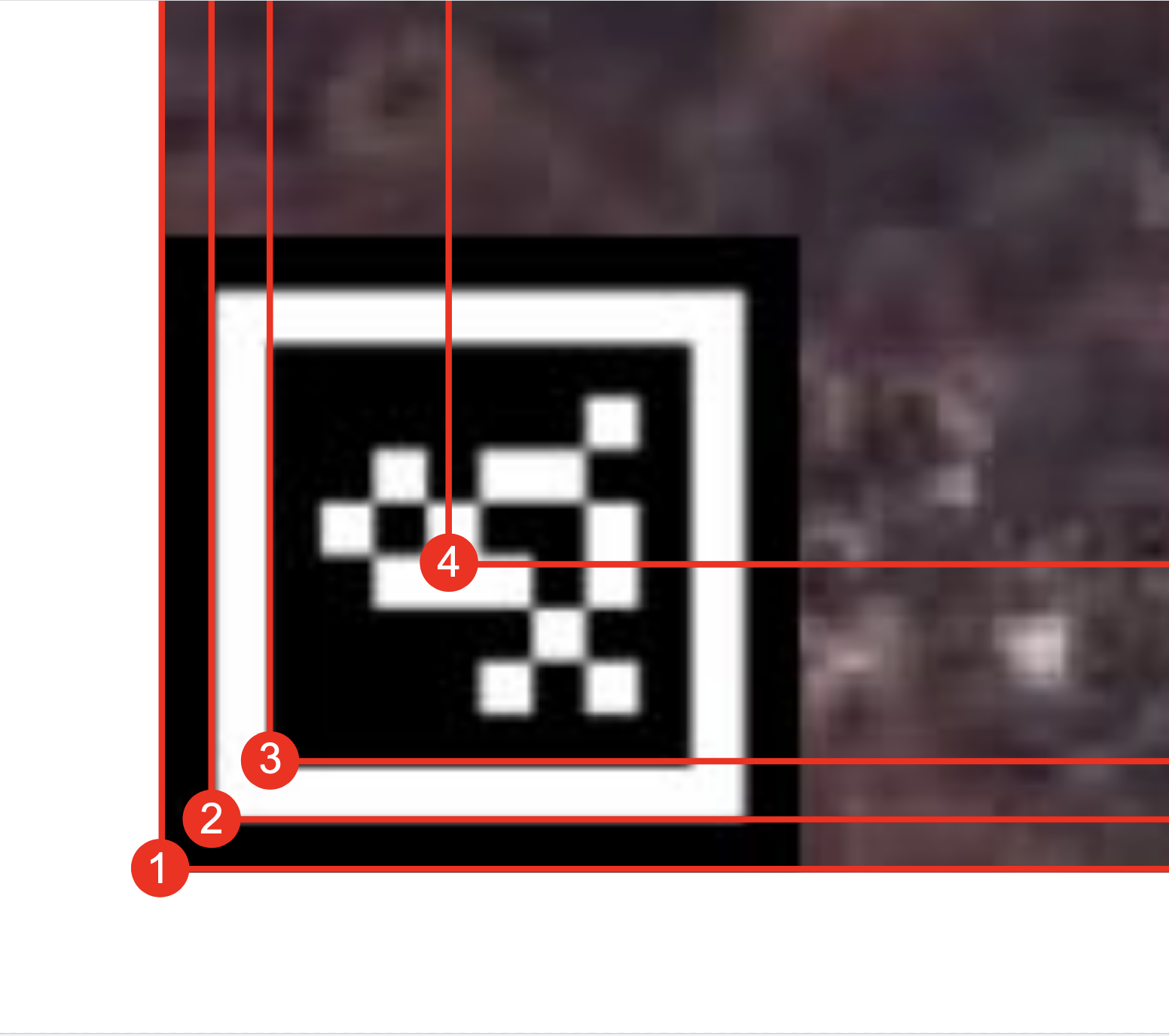
@user-94f03a The orientation of the normalized surface coordinate system is not necessarily aligned with the marker positions. During the creation [email removed] of the surface you have the ability to move the surface corners to wherever you want them. See the image in Younji's message: you can move the corner handles there arbitrarily. https://discord.com/channels/285728493612957698/633564003846717444/1075469281288007760
When clicking the create surface button though, the default surface that is created (and can be customized from there) will be a rectangle that sits tight around the convex hull of the markers. Assuming your markers form a perfect rectangle, the surface would be aligned with the corners markers like ~~rectangle 2 in your example image~~. Edit: Sorry, I meant rectangle 3!
Assuming you have the red bar on top, like you have in your screenshot, the (0,0) corner would be in the top left.
fuh! I was wondering wny you wrote 2 as well ! 🙂 perfect then its point 3, that's what I gathered too. so to map pupil coords with pixel coordinates, i will need to remove the white buffer from the pixels space, i.e. 1920 - 20 (left) - 20 (right) etc.
Either that, or you move the default corners into the actual screen corners! And just to be sure: the white border around the inner marker is a requirement for detection, so please do not remove that. The black outter border might not be needed.
thanks @marc
that's a good idea too, but in our setup we don't get any closer to the tags from what you see in the image above, so i dont have enough resolution to make this adjustment precise enough, at least with the default we know 100% where the corners 0,0, etc are.
Hi! I was investigating the sampling frequency of the gaze data, and I realised that the timestamp are not given at a consistent difference. I find that the time between gaze sample is of 0.004s generally except for every 4 sample where it is 0.008s, is that normal?
Yes, this is expected. The exact reason for this is rather complicated and has to do with how the USB transfer works. Essentially timestamps get created on the phone when the phone receives images from the cameras through the USB connection. The USB connection transfers data at specific cycle speeds and for some samples adds this slight distortion if a transfer cycle is "missed".
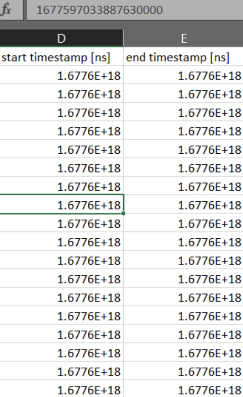
Hi! I’m looking at fixation data, and having trouble reconciling the start time step. This fixation happened at 6 video seconds, and even when I convert from nano seconds to seconds I don’t get a reasonable number. I have also tried truncating the data in various ways. Could you advise how these relate to video time?
Hi @user-0151ab!
To obtain the relative time (time from the beginning of recording), you need to subtract the starting timestamp of the recording. These timestamps you see there are in Unix format, which measures the time elapsed since January 1st, 1970 UTC.
You can find the timestamp you need to subtract in the start_time value from the info.json file.
Hi! We are controlling starting and ending of the recording over NDSI and sometimes we get this sensor failure during recording. So we had to restart the phone and record again. How can we able to avoid this sensor failure?
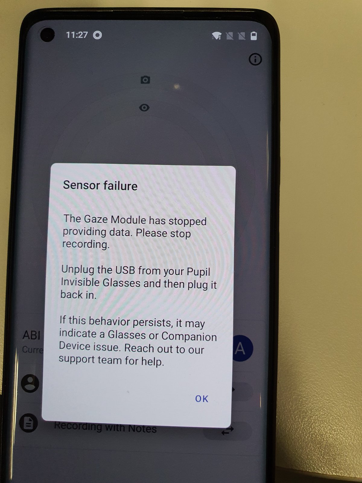
Hi @user-b10192 👋. Please reach out to info@pupil-labs.com in this regard